Bode diagram Solved use matlab to plot the bode diagrams of the system Clase 8: programación de la función de transferencia y de su diagrama
How to Make a Bode Plot Using MATLAB - YouTube
Matlab tutorial: how to generate bode plots for control systems Matlab: bode plot diagram Bode diagram plot gain response compensator magnitude control mathworks drag matlab simulink ug help computes app plots
Bode matlab detailed
Control systems- bode plots can be created directly by using in matlabMatlab program to plot bode and root locus plot for the given transfer How to make a bode plot using matlabMatlab script to plot the magnitude and phase of the continuous complex.
Solved plotting a bode diagram using matlab for thePlot bode matlab locus transfer both Bode command matlab transcribedSolved use matlab to plot the bode diagrams for: (s) =.

Solved bode diagrams: for each part plot both the magnitude
Bode diagram designBode diagram integrator state steady error plot matlab control zero mathworks adding frequency time rise pole increase ug editor help Solved 2. look at the bode plot of the following systems,Bode plot example.
Solved 1. calculate bode diagram for the transfer functionsSolved please help with all parts (plotting the bode Bode matlab plot using make script afkomstig vanBode plot matlab.

Bode plot simulink simulation matlab visualize response during model mathworks completes resembles window following figure after slcontrol ug help
Solved (i) use the matlab bode command, bode (n, d,Bode matlab Bode diagram designBode diagram plots control matlab mathworks response time gain simulink rise ug help automatically update.
Visualize bode response of simulink model during simulationUse program cc to plot the bode diagrams for Solved make the bode diagram of the following transferBode diagram design.

Matlab bode plot
Solved using matlab, plot the bode diagram of the followingSolved consider the system and bode plots in our problem 27 Solved use matlab to plot bode diagram and explain how eachBode diagram.
Bode cutoff response fase frecuencia diagrammi tia diagramma passa lpf filtro grafico amplifier transimpedance basso function lowpass ganancia equation 3dbBode plot order phase matlab first system example filter transfer pass function low high diagram magnitude slope db gain decade Solved matlab bode diagram transcribed textBode plot example.

Bode ordre matlab diagrammes 2ème
Si, ptsi, pt, exemples de programmation avec matlab bode second ordreBode matlab output Solved 1) using matlab, plot bode diagrams of g1( s) and g2Matlab bode diagram.
Solved use 'bode' command in matlab and verify the results .


Bode Diagram | 101 Diagrams

Solved Bode Diagrams: For each part plot both the magnitude | Chegg.com
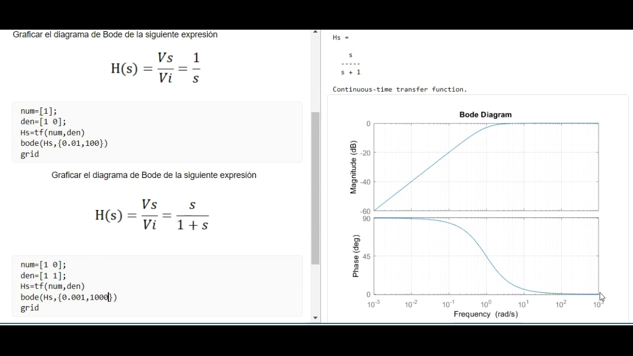
Clase 8: Programación de la función de transferencia y de su diagrama

Matlab Program to plot Bode and Root Locus plot for the given transfer

MATLAB Tutorial: How to Generate Bode Plots for Control Systems - YouTube

Solved - Use Matlab to create the Bode plot for the system | Chegg.com

Solved Use 'bode' command in MATLAB and verify the results | Chegg.com
